Introduction
As modern manufacturing transforms towards high precision and high added value, CNC machining technology has become a core support due to its stability and flexibility. However, when faced with special machining requirements such as high-hardness forged materials, ultra-thin-walled investment castings, and core pin holes in die casting. The physical properties and structural characteristics of the materials themselves often lead to a series of process challenges.
This article will focus on three core scenarios: Hard Turning Post-Forging (45-65 HRC Rockwell hardness post-forging hard turning), Thin-Wall Machining for Investment Castings, and Core Pin Hole CNC Finishing for Die Castings. It will deeply analyze the impact of material properties on machining, dissect the underlying logic of process pain points, and systematically elaborate on targeted solutions.
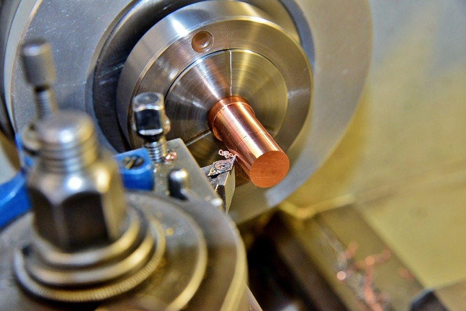
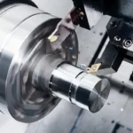
Hard Turning Post-Forging (45-65 HRC): A Breakthrough in Cutting High-Hardness Materials
1. In-depth Analysis of Material Properties
Hard turning after forging typically involves metal workpieces that have undergone forging, strengthening, and heat treatment, achieving a Rockwell hardness of 45-65 HRC. Common materials include alloy structural steels (such as 40CrNiMoA), die steels (such as H13), and stainless steel forgings.
The forging process refines the grain size and densifies the material, significantly improving its strength and hardness. However, it also introduces two key characteristics: firstly, high yield strength and wear resistance, leading to significant stress concentration within the material and a substantial increase in the impact load on the cutting tool during cutting.
Secondly, non-uniform microstructure, where forged materials may contain localized hard spots, oxide scale, or decarburized layers, with hardness fluctuations reaching 5-8 HRC, posing a significant challenge to cutting stability. Furthermore, materials in this hardness range are close to the tolerance limits of traditional cutting tools. Ordinary high-speed steel tools are almost inadequate, and even cemented carbide tools are prone to rapid wear.
2. Core Process Challenges
Severe Tool Wear: During cutting high-hardness materials, the tool’s rake face undergoes severe mechanical and chemical wear, while the flank face experiences severe boundary wear under compression. This significantly shortens tool life, and frequent tool changes not only affect machining efficiency but also reduce workpiece dimensional consistency.
Difficulty in Controlling Machining Accuracy: The large cutting forces generated during hard turning can easily induce vibrations in the machine-tool-workpiece-tool system, leading to excessive workpiece surface roughness (commonly Ra > 1.6 μm) and potential issues such as roundness and cylindricity errors.
Significant Thermal Impact of Cutting: High-hardness materials have low thermal conductivity during cutting, making it difficult to dissipate heat quickly. A large amount of heat concentrates in the cutting area, leading to tool softening and workpiece thermal deformation. This is especially problematic for thin-walled forgings, where thermal deformation can lead to dimensional deviations.
3. Targeted Solutions
Tool Selection and Optimization: Employ PCBN (polycrystalline cubic boron nitride) tools or CBN-coated tools. These tools achieve a hardness of 3000-4000 HV and have wear resistance 10-20 times that of cemented carbide, effectively meeting the cutting requirements of high-hardness materials. Tool geometry parameters need targeted design. A negative rake angle (-5°~-10°) should be used to enhance cutting edge strength, and a clearance angle of 8°~12° should be used to reduce friction between the flank face and the workpiece. The cutting edge needs to be passivated (edge radius 0.02-0.05mm) to prevent edge chipping.
Cutting Parameter Optimization: Adopt a cutting strategy of “low cutting speed, large feed rate, and small depth of cut”. Cutting speed is controlled at 80-150 m/min (adjusted according to material hardness; higher hardness requires lower speed), feed rate is 0.1-0.2 mm/r, and depth of cut is no more than 0.2 mm per pass. Layered cutting reduces the load per cut, thus lowering vibration and tool wear. Simultaneously, high-pressure cooling technology (cooling pressure ≥10 MPa) is employed to precisely deliver cutting fluid to the cutting area, quickly removing heat and flushing away chips to prevent them from adhering to the tool.
The rigidity of the process system is enhanced by optimizing machine tool selection, prioritizing high-rigidity CNC lathes, and controlling spindle speed fluctuations within ±1%. Hydraulic chucks or fixtures with centering functions are used to ensure secure workpiece clamping with a clamping deformation ≤0.01 mm. The tool holder uses a large-diameter, short-overhang design with an overhang-to-diameter ratio not exceeding 3:1, improving tool system rigidity and suppressing cutting vibration.
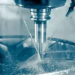
Thin-Wall Machining for Investment Castings: Precision Protection of Ultra-Thin Wall Structures
1. Material Properties and Structural Characteristics
Ultra-thin wall workpieces (wall thickness < 1mm) cast in investment casting are commonly found in aerospace, medical devices, and other fields. Materials are mostly high-temperature alloys (such as Inconel 718), titanium alloys (such as Ti6Al4V), or stainless steel (such as 316L). The core characteristics of these workpieces are low rigidity and high deformability. A wall thickness of less than 1mm results in extremely poor load-bearing capacity; any slight external force or temperature change can cause permanent deformation.
Secondly, the investment casting process may lead to casting defects on the workpiece surface (such as micropores, sand holes, surface roughness Ra>3.2μm), and the wall thickness distribution may have a deviation of ±0.1mm, introducing uncertainty into subsequent processing. Furthermore, high-temperature alloys and titanium alloys are inherently difficult to cut, with high cutting force coefficients, further exacerbating the challenges of ultra-thin wall machining.
2. Core Process Challenges
Severe Clamping Deformation: Traditional clamping methods (such as direct clamping with a three-jaw chuck) generate significant radial pressure, leading to elliptical deformation or localized indentations in ultra-thin-walled workpieces. Deformation can reach 0.1-0.3mm, directly impacting machining accuracy.
Cutting Vibration and Chatter: The radial cutting force generated during the cutting process causes elastic deformation in ultra-thin-walled workpieces, creating a vicious cycle of “cutting force – deformation – increased cutting force,” triggering chatter and resulting in ripples and vibration marks on the workpiece surface, or even workpiece breakage.
Difficulty in Controlling Dimensional Accuracy and Geometric Tolerances: Due to the poor rigidity of the workpiece, factors such as cutting heat and tool wear during machining can cause dimensional drift, making it difficult to guarantee wall thickness tolerances (typically ±0.02mm) and geometric tolerances such as flatness and roundness.
3. Targeted Solutions
Flexible Clamping Technology Application: A clamping scheme of “soft jaws + auxiliary support” is adopted. The soft jaws are made of polyurethane or aluminum alloy. By turning the soft jaws to fit the workpiece surface, the contact area is increased, and the pressure per unit area is reduced (pressure ≤ 0.5MPa). For cylindrical ultra-thin-walled workpieces, an internal hydraulic expansion clamp is used. The uniform pressure of hydraulic oil is used to achieve centering and clamping of the workpiece, and the expansion deformation is controlled within 0.005mm. In addition, rubber pads can be attached to the clamping area to further buffer the pressure and avoid damage to the workpiece surface.
Cutting parameters and tool optimization: Select sharp cutting tools to reduce cutting forces. Preferably use PCD (polycrystalline diamond) or ultrafine-grained cemented carbide tool materials, with a rake angle of 15°~20° and an edge sharpness Ra≤0.02μm. Adopt a “high cutting speed, small feed rate, and minimal depth of cut” approach. Cutting speed: 150-300 m/min (adjusted according to material), feed rate: 0.02-0.05 mm/r, depth of cut: 0.01-0.03 mm. Minimize workpiece deformation through micro-cutting. Simultaneously, employ dry cutting or micro-lubrication (MQL) technology to avoid the impact of cutting fluid on ultra-thin-walled workpieces. If cutting fluid must be used, the pressure must be controlled below 0.5 MPa, and a mist spray should be used.
Machining Path and Process Planning: A symmetrical machining path is adopted, such as cutting from both ends of the workpiece towards the middle, or alternating clockwise and counterclockwise cutting, to counteract residual stress and deformation caused by unilateral cutting. For complex-shaped ultra-thin-walled workpieces, a process route of “roughing – semi-finishing – aging treatment – finishing” is used. After roughing, stress-relieving aging treatment (such as low-temperature annealing, temperature 200-300℃, holding for 2-4 hours) is performed to eliminate residual machining stress before finishing to ensure dimensional stability. In addition, constant linear velocity cutting (G96) is used during finishing to ensure uniform cutting speed on the workpiece surface and improve surface quality.
Core Pin Hole CNC Finishing for Die Castings
1. Structure and Material Properties of Core Pin Holes in Die Castings
Core pin holes in die castings refer to high-precision hole structures formed by core pins in die castings. They are commonly found in automotive parts (such as gearbox housings and engine blocks), electronic device housings, etc., and are mostly made of aluminum alloys (such as ADC12), zinc alloys (such as Zamak 5), or magnesium alloys. The core characteristics of mandrel holes are high precision requirements and complex internal structures. They typically require a hole diameter tolerance of IT6-IT8 and a surface roughness Ra≤0.8μm. Some hole structures also exhibit complex features such as large depth-to-diameter ratios (≥10:1), stepped holes, and intersecting holes.
Secondly, the inner walls of die-cast mandrel holes may contain casting defects such as burrs, flash, oxide scale, micro-shrinkage cavities, or porosity. These defects affect machining accuracy and surface quality. Furthermore, while materials like aluminum alloys and zinc alloys have good machinability, their high toughness makes them prone to generating built-up edge during cutting, leading to scratches on the inner walls of the holes.
2. Core Process Challenges
Difficulty in Handling Inner Wall Defects: Burrs, oxide scale, and other defects on the inner walls of mandrel holes are unevenly distributed and difficult to completely remove using traditional machining methods. Residual defects can affect subsequent assembly accuracy and sealing performance.
A large aspect ratio leads to machining difficulties: For core pin holes with an aspect ratio ≥ 10:1, the large tool overhang and insufficient rigidity make the tool prone to vibration and runout, resulting in enlarged hole diameter and increased roundness error. Simultaneously, chip removal is difficult, easily causing chip blockage, scratching the inner wall of the hole, or damaging the tool.
Surface quality and dimensional consistency control is difficult: The toughness of die-cast materials makes it easy to generate built-up edge during cutting. Built-up edge detachment forms scratches on the inner wall of the hole, affecting surface roughness. At the same time, the die-cast part may have a loose internal structure, easily causing dimensional fluctuations during machining, making it difficult to ensure dimensional consistency in mass production.
3. Targeted Solutions
Tool Selection and Structure Optimization: For core hole machining, specialized deep hole machining tools are selected, such as solid carbide gun drills, reamers, or boring tools. The tools must possess good rigidity and chip removal performance. The helix angle of the gun drill is 30°~40° to facilitate chip removal; the reamer adopts a multi-flute design (4-6 flutes) with polished cutting edges (Ra≤0.01μm) to reduce built-up edge formation; for stepped or intersecting holes, indexable boring tools are selected, allowing for multi-stage machining by changing different tool tips, reducing tool changes. Furthermore, TiAlN or CrN coatings are used for the tools to improve wear resistance and lubrication, reducing cutting forces.
Machining Process and Parameter Optimization: A composite machining process of “drilling-reaming-reaming” or “drilling-boring-honing” is adopted to gradually improve the hole’s accuracy and surface quality. When drilling, a center drill is used for pre-positioning to ensure the coaxiality of the hole; when reaming, the cutting depth is set to 0.2-0.5mm to correct drilling errors; when boring, the feed rate is set to 0.08-0.15mm/r, and the cutting speed is set to 20-50m/min to ensure the dimensional accuracy and surface roughness of the hole.
For holes with a large depth-to-diameter ratio, a pecking cut (G73) is used, with a certain distance (0.5-1mm) retraction after each feed to facilitate chip removal. Simultaneously, a high-pressure internal cooling tool is used to deliver cutting fluid from inside the tool to the cutting area, flushing away chips and cooling the tool.
Defect pretreatment and quality control: Before machining, the core pin holes of the die-cast parts are pretreated by flushing the inner wall of the hole with a high-pressure water gun (pressure ≥20MPa) to remove burrs, oxide scale, and other impurities; for workpieces with defects such as shrinkage cavities and porosity, repair or screening is carried out in advance to avoid affecting the machining quality. Online inspection technology is employed during the machining process. The hole diameter is measured in real time using a contact probe mounted on the machine tool. Based on the measurement results, tool offset is automatically compensated (compensation accuracy ±0.001mm) to ensure dimensional consistency in batch production.
In addition, after finishing, a honing process is used for ultra-precision machining. The honing head speed is set at 1000-1500 r/min, and the feed rate is set at 0.01-0.02 mm/r to further reduce the surface roughness to Ra≤0.4μm.
Common Technological Logic and Industry Application Prospects for Three Major Scenarios
Whether it’s high-hardness forging post-machining, ultra-thin-wall investment casting machining, or die-casting core hole finishing, the core technological logic of CNC machining revolves around four dimensions: “material property adaptation, process system rigidity enhancement, cutting parameter optimization, and quality closed-loop control.” The key to machining high-hardness materials is overcoming tool tolerance limits and vibration control; the core of ultra-thin-wall machining is solving clamping deformation and chatter problems; and core hole machining focuses on defect handling and deep hole machining challenges. Although each has its own emphasis, all three require synergistic optimization of tools, machine tools, fixtures, and processes.
As the manufacturing industry moves towards intelligent and precise manufacturing, the technologies in these core machining scenarios will continue to upgrade: In the cutting tool field, new superhard materials (such as CBN composite tools and diamond-coated tools) will further improve cutting efficiency and lifespan; in the machine tool field, the widespread adoption of five-axis CNC machine tools and high-speed precision machine tools will enhance machining flexibility and accuracy; in terms of intelligent manufacturing, AI-driven adaptive adjustment of cutting parameters and process simulation optimization using digital twin technology will achieve precise control of the machining process.
In the future, the integrated application of these technologies will bring higher production efficiency and better product quality to the CNC machining industry, promoting high-quality development in fields such as aerospace, automotive manufacturing, and medical devices.
Complete Guide to Understanding Pipe Flanges
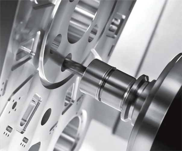
Advanced CNC Machining for Automotive and Industry